Design Goals
- Variable speed using PWM
- “Safe” circuit with no chance of a short circuit
- minimal pin count
Notes
I don’t think I mention it below, but I chose the particular model of NFET because it was the same one that was used in the original drill that I pulled the motor from. The NFET there also had a decent sized heatsink attached to it, so that could have been another source of problems.
I also considered using a TVS diode to suppress the motor surge. Again, I have not tried this to see if it would have made any difference.
I found out much later that most of my problems with the solid-state solution were probably because of the way that I was driving the NFET gates. A proper gate driver will be able to provide the necessary voltage to the high-side gates, will provide the necessary current to ensure fast switching, and will add a delay to eliminate any shoot-through current (where both NFETs on one side are active at the same time, creating a short circuit).
Version 1.0
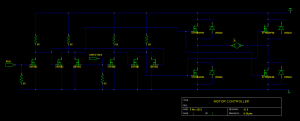
This is the original design I came up with. The right side it a standard H-bridge circuit using NFETs, and the left side is some NMOS logic to control the H-bridge.
One of the difficulties of using NFETs in this H-bridge is that the voltage to the gate must be fairly close to +9V for things to work properly. Once current begins flowing through the motor, the voltage at the NFET source on the high side will rise. If that voltage rises too close to the gate voltage, then the device will begin to operate in the linear region, where the current through the device will begin to be restricted. Obviously, if I try to use a +5V signal from my microcontroller, I’ll run into this problem. My solution is the NMOS logic on the left.
For those unfamiliar with NMOS logic, the circuit that I show implements the following (where A and B represent the 2 inputs to the H-bridge):
A = ~( ~RUN | ~DIRECTION ) = RUN & DIRECTION
B = ~( ~RUN | DIRECTION  ) = RUN & ~DIRECTION
Because the high-side of the NMOS is +9V, its output will be able to drive the H-bridge without problem. Also, since the source terminal of each NFET in the NMOS logic is tied to ground, it can easily be driven by 5V signals from my microcontroller.
The last things to note in the schematic are the bypass diodes in the H-bridge. I added these to help dissipate the voltage spike produced from the motor. Since the motor is a highly inductive load, when the motor is turned off it will try to maintain the current that was going through it. If not shunted, this can cause a severe voltage spike.
I didn’t actually build this design first because I had another idea that I call V1.1.
Pros
- solid state
- only 1 PWM input is required (other input can be a regular I/O pin)
- inputs are 5V compatible
- only 1 voltage source required (the drill battery)
Cons
- Unknown…not tested (yet)
Version 1.1
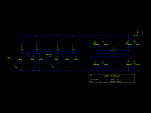
When I ordered my parts, I added an extra 1 or 2 of each type just in case I burnt one up, or to make the next pricing bracket (sometimes it’s cheaper to buy 5 instead of 4). Since I had 5 diodes, I figured, “Why not make it idiot-proof?” If I accidentally hooked the batter up backwards to V1.0, I’d see a ton of current dumped through my bypass diodes, and I’d either end up with some burnt diodes or a dead battery. I added the fifth diode to make sure that nothing would happen if I did connect the battery backwards.
Unfortunately, I didn’t realize at the time that this also hampered my plan to deal with the motor-produced voltage surge. I was relying on the surge current flowing backwards into the battery, and when I added the “idiot-proof” diode, that current surge no longer had anywhere to go.
When I connected everything and tested the circuit, I was elated because the circuit worked! When I connected RUN to 5V, the motor ran, and when I disconnected it, the motor stopped. Then I tried again, and it didn’t do anything. I quickly realized my voltage surge problem, and realized that it had taken out some part of my NMOS logic. Fortunately, only 1 NFET burnt out, and it was easy to identify the problem and replace the NFET.
Pros
- “Idiot proof”
Cons
- motor surge kills NMOS
Version 1.2
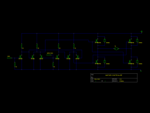 You’ll notice that this circuit is familiar…yes, it’s exactly the same as V1.0 that I hadn’t actually built. After I realized that my “idiot-proof” diode was preventing the surge from dissipating in the battery, I removed it and tried again.
I connected everything again being very careful of the battery polarity this time, since I didn’t have my protection diode. I began the testing. When I connected RUN to 5V, the motor ran, and when I disconnected it, the motor stopped. Knowing that this was where things broke last time, I connected RUN to 5V again, and the motor ran! I probably flipped it on and off 5 or 10 times, and to my amazement, it kept on working! The battery was absorbing enough of the spike to keep things functioning.
“Time for phase 2 of the testing,” I thought to myself. While I had RUN at 5V, I’d toggle DIRECTION to see if the circuit could tolerate switching direction.
Unfortunately, it couldn’t.
The current/voltage spike is much greater switching direction than simply stopping the motor, and once again, it proved to be too great for my NMOS logic, and too great to be absorbed by the battery.
Pros
- works perfectly in one direction
Cons
- motor surge kills NMOS when switching direction
Version 1.3
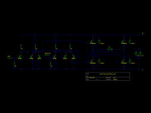 At this point, I needed something that could sink the surge from the motor. My NMOS couldn’t handle the surge, and the battery apparently couldn’t sink it fast enough. I figured that a couple of zener diodes across the battery would probably solve my problem.
Since my deadline (Halloween) was looming, I didn’t have time to order anything. I figured I’d give Radio Shack a shot, and amazingly, my local store actually had zener diodes in stock! I was skeptical that they would be able to sink the magnitude of current that I was likely dealing with, so I connected two in parallel.
I began my testing, and quickly discovered that my skepticism was justified. The zener diodes burnt. At least this time I got the satisfaction of a little magic smoke from the diodes. The repeated stresses must be taking their toll on my NMOS, because this time 3 NFETs burnt up (instead of 1 each in the previous tests).
As an aside: even if I had enough time to order zener diodes through a proper supplier, I’m not sure that my initial outcome would have been much different. I had (and still have) no idea the magnitude of the current surge that I was dealing with, so I may still have bought woefully under-rated parts that I thought might work. It is quite plausible, however, that this approach would work with a properly sized zener diode or avalanche diode.
I also realized much later that a capacitor might have helped. Upon further pondering, however, I’m not sure that it would have worked so well. In order for the capacitor to have effectively absorbed the surge, it would have to have a very large capacitance. However, a very large capacitor would have to be charged every time connected the battery, and discharged every time that I disconnected the battery before I could safely work on the circuit. It is a potential solution, but probably not ideal.
Pros
- in theory, it could work…
Cons
- in practice, it didn’t
Version 1.4
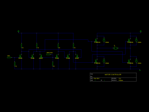 At this point, I had had enough of these voltage surges killing my NMOS. (And I was running out of NFETs to replace them with!) I decided that the best way to isolate the NMOS logic from the surge was to put it on its own power supply. The battery that I was using up to this point was a 9.6V NiCad pack, so I continued using that to power the H-bridge, and used a 9V battery to power the NMOS.
When I connected everything, it all worked as expected. I could start and stop the motor going in one direction, I could start and stop the motor going in the other direction, and I could change direction while running.
Then, things started smelling. Anyone who has burnt up electronics knows the smell…hot metal and plastic. Shortly after the smell, things stopped working, and the smell persisted. I quickly unplugged everything, and felt for the hot component. It turned out that all of my power NFETs were scorchingly hot. After I let everything cool down, I tested the circuit again, but it was too late. I had burnt up 2 of my high-current NFETs.
I don’t know exactly what happened to burn up those components, but I have a couple of theories. First, of course, is that the power surge from changing the direction of the motor was still too much for even the large NFETs to handle. Since there weren’t any weaker components in the surge path that could break and take the surge, the full magnitude of the surge remained across the H-bridge, and must have been greater than the 60V that those components were rated for.
My other guess is that the gate voltage to the NFETs on the high side of the H-bridge was not high enough for the devices to operate in the “active state”, and were instead operating in the “linear range” where they provide much more resistance to the current, and therefore much more heat. Is it possible that I simply overheated the parts to the point of failure.
After performing a post-mortem on the circuit, however, I think I’ve convinced myself that the second guess could not have been the only cause of failure (but still may have contributed). Only 2 of the NFETs failed, and one was on the low-side of the H-bridge where operating in the “linear range” would not have occurred.
Pros
- NMOS logic was spared
Cons
- power surge or poor design still destroyed the circuit
Version 2.0
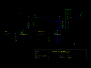 At this point, saying that I was somewhat frustrated would be an understatement. I was ready to give up on the project altogether because
- I only had 1 replacement high-current NFET, and I needed 2
- I couldn’t think of a good way to suppress the surge from the motor
- I only had about 36 hours until Halloween
That night, in my tumultuous sleep, I had an idea. I vaguely remembered seeing relays at my local Radio Shack, and it might be possible to loosen my design goals (especially PWM speed control) and create a bi-directional controller out of a couple relays.
Thus, Version 2.0 was born.
I did manage to find 2 suitable relays in my local store: a SPDT relay and a DPDT relay, both rated to handle 10A and both having a coil voltage of 12V.
5V (and low-current) from my microcontroller obviously wasn’t going to work to drive the relay coils, but when I hooked up the coils from each relay to the 9.6V battery I had, they both triggered. I pulled the remaining functional high-current NFETs off of my previous design to handle switching the coil current, and re-used the bypass diodes to try to deal with the coils’ inductive loads as well.
when I connected everything except the motor, everything worked perfectly! I could connect RUN to 5V, and the first relay triggered. When I connected DIRECTION to 5V, the second relay triggered too!
However, when I hooked up the motor and tried again, the motor only would only run in one direction. It turned out that the motor’s load dropped the battery voltage enough that it was no longer enough to power the DPDT relay’s coil.
It was probably fortunate that the DPDT relay wouldn’t flip. Since the NFETs were again on the same power source as the motor, I wouldn’t be surprised if the motor surge would have burnt up an NFET again.
Pros:
- works perfectly with no motor load
Cons:
- motor load drops battery voltage enough that relay won’t trigger
- still possibility of motor surge doing bad things
Version 2.1
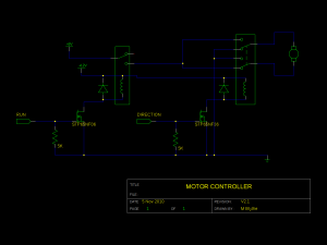 After I dug a 12V wall wart out of my box of surplus electronics, I altered my circuit to have separate voltage supplies for the relays and the motor.
This time, finally, when I connected everything, it actually worked. The drill ran forwards, backwards, and was able to switch directions while spinning.
Once I integrated it into the rest of my system, however, I noticed that the motor’s momentum caused it to continue spinning quite a while after I had cut power. This was a problem because of the way that I was counting revolutions.
Pros:
- motor spins, and changes direction.
Cons:
- when power is cut, the motor keep spinning for a while.
Version 2.2
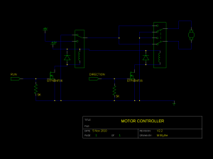 I fixed this little hiccup by flipping the SPDT relay around so that the normally-closed connection shorted out the motor. This has the effect of braking the motor, similar to regenerative braking except that the kinetic energy of the motor is just dissipated as heat instead of being stored and reused.
Now, when I cut power, the motor stopped much more quickly, so a delay between directions was more acceptable.
Finally, my motor controller was finished! Unfortunately, this was also too close to Halloween to get everything else together. Oh well, there’s always next year!
